Cookie
Electronic Team, Inc. uses cookies to personalize your experience on our website. By continuing to use this site, you agree to our cookie policy. Click here to learn more.

Communicate between AVR and PC using Virtual Serial Port

Olga Weis Olga Weis

This article will talk about how to communicate between AVR and PC in a simple but quite comprehensive way. It's simple because I'm going to use a rather "classic" interface to communicate between AVR and PC, RS232 interface via COM ports. Comprehensive as I will guide you through the transition between AVR and PC, how to write program interface RS232 on the computer and on the AVR. Specifically this article includes:

Contents


  1. Schematic diagram and function of the COM port pins on the computer. AVR circuit to PC via COM port.
  2. Create a virtual COM port on the PC for simulation purposes.
  3. Use functions in standard C export library such as printf, scanf ... in WinAVR.
  4. Write COM port program on PC (Visual C ++, Visual Basic)

1. COM port overview


A COM port or Serial Port is a communications port that is part of the "aging" form of the PC, both desktops and laptops. Today, with the emergence and "expansion" of the USB standard, the COM port (and either the LPT port or the parallel port) is disappearing.

COM port communication is RS232 serial communication. This standard is quite slow compared to USB. However, with the robotics or control, the COM-RS232 is very popular for its simplicity and also because of ... this slowdown. COM ports on existing computers (where available) are mostly 9-pin male. However, somewhere there is a 25-pin COM port, which is about the same as the LPT port, but it's a male, while the LPT port is female.

Need to understand main points about null modems and pinout RS232.

Figure 1 shows two types of COM ports and Table 1 summarizes the functions of the ports.

9-pin COM and 25-pin COM Port
Figure 1.

pins on the COM port
Table 1

Most noticeable in the pins of the COM port is the 3 pin 0V SG (signal ground), TxD data transmitter pins and RxD data receiving pins. These are three basic pins for RS232 communication and UART compatible on AVR. The remaining pins can also be used if the user has some knowledge of the PC's register organization. In most cases, however, only three pins are used.

As stated in AVR5-UART, the RS232 and UART standards are generally the same in terms of transmission, baud rate ... but vary in voltage and polarity. Refer to the comparison example in Figure 2.

Compare UART and RS232
Figure 2.

In UART standard (on AVR), level 1 corresponds to high voltage (5V, TTL) while for RS232 level 1 corresponds to low voltage (negative voltage, maybe -12V). Clearly there is a need for a "converter" between the two.

Fortunately, we do not need to design this bridge ourselves because there are dedicated ICs. MAX232 is one of the most used UART-RS232 switch ICs. Of course, you can create a simple circuit with just a few components such as capacitors, resistors, diodes and transistors but stability is not guaranteed.

Figure 3 shows how to use the Max232 IC to connect between UART on AVR and PC COM port.

Connect AVR to PC via Max232
Figure 3.

The above circuit only has the effect of varying the voltage level between RS232 and UART. It does not change the communication mode of these standards and so programming on PC and AVR is not a substitute, change. In fact, Max232 has two transoms.

In Figure 3, we only use transceiver 1. TxD pin (pin 3) of the COM port connected to the R1IN (Receive 1 Input) of Max232 is corresponding to the R1OUT (Receive) 1 Output) must be connected to the receiver RX of the AVR. Same for T1IN and T1OUT. The value of the 10uF capacitors is relatively standard, but when you replace the capacitor with 1uF, the circuit remains active but the transmission distance (cab connector) will be shorter (if too long will generate communication error). The resistors in Figure 3 only work to protect COM ports and ICs, so you may not need to use these resistors without affecting the operation of the circuit. Vcc and GND are sources of AVR circuits.

Note: If you want to communicate between two computers together via COM port, you need to use 1 crossover cable (PCx's TxD pins connected to RxD of PC2 and vice versa) to connect 2 COM ports together.

2. Create virtual COM port for simulation


To make communication between AVR and PC via COM port you obviously need a COM port, in addition you need to make an AVR circuit and bridge the Max232. Unfortunately, not all computers have this port. If you just want to learn how to communicate with AVR-PC or just want to test a particular algorithm, perhaps simulating the solution is preferable. For the purpose of simulating RS232 communication, Proteus is again useful for simulating data transmissions with COM ports.

So the problem is how to create virtual COM ports on the computer and connect them together to perform communication simulations. Because of the nature of the COM port is only "open" (open) only once, meaning that the two software can not open the same port.

Our idea is to create two virtual COM ports that are "crossed" together (eg COM2 and COM3). In the Proteus output of the UART is connected to COM2. In PC software (for example, HyperTerminal) we connect to COM3. In this way we were able to communicate between the AVR (Proteus model) and the PC (HyperTerminal software).

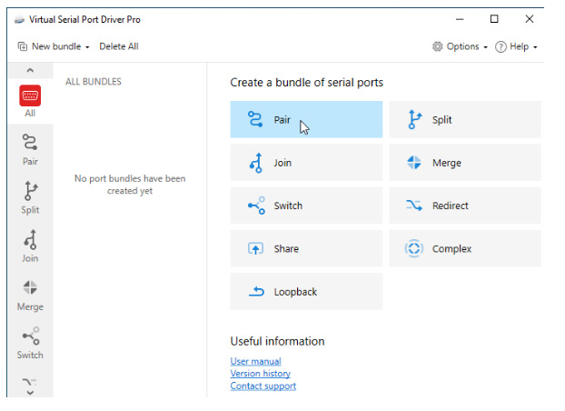
There are some good software that can create virtual COM ports and virtual connections between them exactly as required by us. In this section I will introduce a software Electronic Team (Virtual Serial Port Driver).

Virtual Serial Port Drive (VSPD) emulates virtual serial ports and connects them in pairs via virtual null modem cable. Applications on both ends of the pair will be able to exchange data in such a way, that everything written to the first port will appear in the second one and backwards.

VSPD is easy to use and stable. After downloading proceed with the installation, find and run the "Add pair" file.

Interface of VSPD as shown in Figure 4.

Virtual Serial Port software interface
Figure 4.

In the "Manager ports" tab, the software automatically suggests that a couple of virtual COM ports can be created, you can select them again and click "Add pair" to create these two COM ports. The virtual COM port created by VSPD appears in the Windows "Device list" and is not lost when the user switches off the VSPD software. Run Windows' Device Manager. In the Ports (COM & LPT) section you will see the virtual COM ports created (see example in Figure 5).

Virtual COM ports and connections between them created by VSPD
Figure 5.

3. Use stdio.h standard export library in WinAVR


Anyone who has ever learned C programming language will not forget his first "hello world" program:

hello, world

This program simply does the job of typing "hello, world" on the screen. Letter print is done by the "printf" command in line 3. The printf command is in the stdio library called the standard input / output library. The printf command in stdio is not just for printing on the screen but can print to any output device, even print a file on a computer hard drive ...

For AVR, if you use the compiler When you call printf, the string is printed (output) the UART module (of course you have to install the UART registers to activate the UART first).

CodevisionAVR itself understands UART as the default input / output device for commands in the stdio library (printf, scanf ...). However, with WinAVR (avr-gcc) everything else is different. To use standard input and output we need to declare an input device and a "basic" input function. The basic function is a function defined by the user, whose task is to export (or import) a character to an input device.

For example, in AVR5 - UART communication we define a function "uart_char_tx" output characters to UART as follows:

uart_char_tx

Or in TextLCD we look at the function "putChar_LCD" to output a character to the LCD as below:

putChar_LCD

Both "uart_char_tx" and "putChar_LCD" as the example above can be used as a "basic" import function for functions such as printf ... in standard sdtio export libraries. Assuming the function "uart_char_tx" is used, when calling the printf function, the string is exported to the UART.

In contrast, if the "putChar_LCD" function is used as the base function, the stdio printf function will output the data string to the LCD. With this method, avr-gcc translator allows us to access the stdio library more flexibly, you can use stdio functions to export / import data to any device such as UART terminal, TextLCD , Graphic LCD or even SD, MMC card ... once you define the "basic" input function.

To illustrate how to use functions in the stdio library, I will show an example of outputting data to TextLCD and uart using stdio's printf .... The circuit simulation for this example is shown in Figure 6 below.

Simulate exemple output example with stdio library
Figure 6.

All of the data displayed on the LCD and the uart terminal in Figure 6 are done through the printf and fprintf functions. Also in this example, the user can enter a character from the keyboard and the ASCII code. of the key will be printed on the terminal. The code shown in List1.

Export data to LCD and UART with stdio standard export library
List 1.

To use the functions in the standard output library, we need to include the library header file as in line 4 "#include ".

Note that when using avr-gcc, avr -libc-related functions are located in the "/ avr /" subdirectory of the include directory.

For example, the header io.h or interrupt.h contains special functions for avr, when attaching these files we specify something like: "#include " ... However, The standard C language (such as stdio.h, math.h, ...) is directly in the include directory, when attaching these files must be written directly as in the code line 4. Also because this example uses LCD, you need to copy and include the library myLCD.h as in line 5 (review TextLCD).

As discussed above, to use the functions in stdio we need basic input / output functions. The lines from 7 through 11 are uart output functions named "uart_char_tx", which will be used as the basis function for the output functions of stdio. The "uart_char_tx" function was discussed in the UART lesson, where a small change was made to the 8 line "if (chr == '\ n') uart_char_tx ('\ r')", this line has meaning that when the user wants to output the character "\ n", the function " uart_char_tx " will output the character '\ r'.

So if you come across a '\ n' (with ASCII code 10, called Line Feed - LF) at the end of the sentence, a combination of '\ r' + '\ n' (code '\ r' = 13 called Carriage Return - CR) will be sent to the stream. To better understand this issue, you will learn more about the Carriage Return Line Feed (CRLF) in Windows.

Two lines of code 13 and 14 are very important when using the stdio library. The meaning of these two lines is to create two virtual "FILE" (also known as stream) for data export. We examine line 14: create a stream for the UART.

static FILE uartstd = FDEV_SETUP_STREAM (uart_char_tx, NULL, _FDEV_SETUP_WRITE);

We create a variable named uartstd (user-named self-named) which is of type FILE (a virtual device type), then uses the "FDEV_SETUP_STREAM" macro to initialize and set the parameters for uartstd. This macro has the function of opening a fdevopen and assigning "tools" for importing into the device.

#define FDEV_SETUP_STREAM (put, get, rwflag)

The attached parameter "FDEV_SETUP_STREAM" consists of a basic function called "put", a basic function called "get" and a flag indicating the output or input function of the device being opened. Specifically, in line 13, the uartstd variable is a "virtual device" used for data output (due to the _FDEV_SETUP_WRITE parameter).

The tool for uartstd output is the "uart_char_tx" function we created above. There is no function for getting data from uartstd (get = NULL parameter). You can imagine this: the uartstd variable is a sheet of paper, the function "uart_char_tx" is a "stamp" that allows printing a character on a sheet of uartstdpaper. We assign "uart_char_tx" to usrtstd then all printing on uartstd paper will be done by "uart_char_tx". The function "uart_char_tx" is therefore called the base function.

Similarly, in line 13 we create another "paper" named lcdstd and its basic function leaves the function "putChar_LCD", which is already defined in the myLCD.h library.

The lines in the main program from lines 17 through 25 start UART and TextLCD, you can review the related articles to understand more. After booting, UART and LCD are ready for data export. Now we can use the functions in the stdio library like printf or sprint ... to export the data. You will see Figure 6 because I will use it to compare against the following lines of code. Line 27 "printf (" In lan 1 "), the purpose is to print the string" In lan 1 "to the LCD using the printf function. However, as shown in Figure 6, you do not see this string appear.

Now look at line 28 "fprintf (& lcdstd,"www.eltima.com")" and look again at Figure 6, this time you have seen the string "www.eltima.com" appear on the LCD, Successful with the fprintf function. The fprintf function is a function that outputs data to a virtual device, where the first parameter of the function points to the device and the second parameter is the data string to print. In this case, we used fprintf to export the "www.eltima.com" string to the lcdstd virtual machine and succeeded. What about the printf function in line 27? Let's look at the lines from 30 to 32. Line 30 we once again use the printf function "printf (" In lan 3 ")" to print the "lan 3" on the LCD but still not successful (see LCD in Figure 6). In line 31 we assign "stdout = & lcdstd" where stdout is a variable (actually a stream or virtual device) of the C language, which defines the default device for data entry. When assigning stdout to lcdstd as line 31, we declare that LCD is the default input device. So, in line 32 we call printf "printf (" Lan lan 4:% i ", x)" we were successful.

This time, look on the LCD you will see the line "Lan Lan 4: 8205" appears. Here 8205 is the value of the variable x in the statement at line 32. In summary, the fprintf function allows direct printing to a specified virtual device while using the printf function we need to assign the input device Precedes for the stdout variable.Take a look at the code from lines 34 through 37 and the first three lines in the terminal in Figure 6, which you probably already know for yourself.

Finally, the UART data interrupt server is in code lines 41 through 44. In this example, we simply execute the " Ma ASCII: " line with the value received from the " The UART is contained in the UDR register: "fprintf (& uartstd," Ma ASCII:% i \ n ", UDR)".

To fully understand the stdio library in WinAVR you need to read the "avr-libc Manual" documentation, the Standard IO facilities section.

4. Programming with COM port using Visual Basic and Visual C ++


In many cases, communication requirements require a higher degree of complexity, such as data storage or variable graphing, so users need to write their own programs on their own. This tutorial shows you how to write programs on a computer to transmit and receive data from a COM port in Visual Basic and Visual C ++ 6.0. Note, the purpose of this article is on AVR, so the application written on Windows I just presented a simple way for you to grasp the principle. To develop more sophisticated applications, readers need to equip themselves with knowledge of Windows programming. In all the tutorials below I assume that the least readers know how to create a project in Visual Basic or / and Visual C ++.

1. Write a COM port program using Visual Basic 6.0


Since the later versions of Windows 2000, communication with traditional computer ports, such as LPT ports, in Windows was relatively difficult. However, with COM ports, it is fortunate that Microsoft provides a tool (actually a control) called "Microsoft Communication Control" or MSComm for short. MSComm has appeared in popular MS programming software such as Visual Basic or Visual C ++ as a "control". As a "controller" designed for COM ports, MSComm contains all the tools needed to communicate with this port, the job of the programmer is simply to declare and use. To illustrate how to use MSComm in Visual Basic, follow the instructions below.

Run Visual Basic 6, go to the "File / New Project" menu and create a "Standard EXE". You will see a Project named "Project1" with a background dialog box named Form1. You can name any project and main form. From the Toolbox toolbar, click on the "textbox" control and draw two main textboxes called txtOuput and txtInput (rename text boxes in the Properties window. in the lower right, right).With txtOutput, set the Multiple parameter to True and ScrollBars to "3 - Both"

Next put the MSComm control into the main form. By default, the MSComm control is not available in the Visual Basic Toolbox, we need to add it to the Toolbox before using it. To add MSComm to the Toolbox, select the "Project / Components" menu. You will see a dialog box named Components. Find and click on the "Microsoft Comm Control 6.0" as shown in the picture and click OK. Now, in the Toolbox of VB you will see the icon of MSComm appear. Click on this icon and draw a MSComm object on the main form. Keep the default name of this object is MSComm1.

Write a code :

The purpose of this example is as follows: Data received from the COM port is displayed on the txtOutput textbox, and when user type 1 characters in the txtInput character will be transmitted over the COM port.

First, doubleclick on the main form, write the following code into the Form_Load () event:

Form_Load

The purpose of this code is to set the parameters for MSComm1.

  • CommPort parameter = 3 means that we want to connect to COM3 port. This parameter varies according to the COM port we want to communicate with.

    Parameter Setting = "38400, N, 8.1" means baud rate = 38400, no parity bit, frame length is 8 and 1 stop bit.

  • RThreshold = 1 means that when there is 1 character to COM port, data receive interrupt will occur.
  • InputLen = 1 means that when reading data from the receive buffer, we will read one character (1 byte).
  • PortOpen = True allowing "open" COM ports to be ready to communicate.


  • Next, doubleclick on the MSComm1 icon on the main form to write the code into the MSComm1_onComm () event:
MSComm1

The onComm() event is essentially an MSComm interrupt handler. When there is one byte of data sent to the buffer of the COM port (the number of bytes specified by the RThreshold), the onComm event will occur, in this event we will write the code to receive and process the data. whether. Line 2 we declare a temporary variable named InputText with string data type. Note that the onComm event can occur for a variety of reasons, where we only care about the case of incoming data, line 3 is a sort of "filter" event, we only execute the line of code whereas the comEvReceive event occurs (the data is retrieved):

If Me.MSComm1.CommEvent = comEvReceive Then. The only important thing to read to the data sent to COM is to read the input buffer of MSComm as in line 4:InputText = MSComm1.Input. After this command the data will be contained in the temporary variable InputText. Next we just increment the characters received into the content of the textbox txtOutput to display on the screen (line 5): txtOutput.Text = txtOutput.Text + InputText. Line 6 is responsible for bringing the cursor to the end of the txtOutput content for easy viewing of the data.

comEvReceive

Finally, doubleclick on the txtInput textbox and look for the KeyPress event to write the following lines of code:

The txtInput_KeyPress event occurs when a user presses a key on txtInput. The line Me.MSComm1.Output = Chr (KeyAscii) does the sending of the value of KeyAscii to the COM port, where KeyAscii is the ASCII code of the key pressed.

You have finished writing the COM port through Visual Basic. To test your program, perform the following simulation:

  • Use VSPD software to create two virtual COM ports COM2 and COM3, cross them together (see COM port section). virtual).
  • Look in the folder containing the AVR_STD example and run the simulation file using the Proteus AVR_STD_Terminal.DSN software.
  • Back to Visual Basic, click the Run or F5 button to run the new project.
  • Click Run in Proteus to simulate the circuit AVR_STD_Terminal.DSN. You will see some text appearing txtOutput. Click txtInput and type any key to see the result. So you have successfully written yourself a COM application with COM port in Visual Basic.

2. Write a COM port program using Visual C ++ 6.0


This part of the tutorial looks at how to use a COM port like the example above but uses Microsoft Visual C ++ (VC ++). The main purpose is to guide how to use MSComm in VC ++, so I will present very sketchy parts like creating a project in VC ++. Readers need to equip themselves with more knowledge about VC ++ programming. One of the great tutorials for beginners is "Teach Yourself Visual C ++ 6 in 21 Days" by Sams Teach Yourself, which you can read if needed.

From VC ++ go to "File / New" menu to create a new project. Select the project type as "MFC AppWizard (exe)", in the Project Name box name the project is AVR_PC, click OK. In the second dialog box select "Dialog based" for the project type, and click Finish to create the project (other steps to default).

When the new project is created, a dialog box appears with the "OK" and "Cancel" buttons on it. Use the "Edit" tool to add 2 "Edit boxes" and rearrange the interface. Right click on the Edit box and select Proterties from the Popup_menu, in turn change the ID of the 2 Edit boxes to IDC_OUTPUT and IDC_INPUT.

As in VB, Control MSComm does not appear by default in the VC ++ Toolbox, which we need to add when we want to use this control. Go to the "Project / Add to Project / Components and Controls ..." menu. When the "Components and Control Gallery" dialog box appears, select the "Registered ActiveX Controls" folder and navigate to the "Microsoft Communications Control, Version 6.0" file and click the insert button, then click OK when asked any questions. Click the Close button to close the dialog box. At this point, the icon of MSComm will appear in the VC ++ Toolbox. Click on the icon of MSComm and draw a control on the main dialog of the project. By default, this control is named IDC_MSCOMM1.

Programming in VC ++ is more difficult than VB (for newbies). Properties of controls such as Edit box are not directly accessible as Textbox in VB. For example, to assign and display a string or number to the Edit box we have to perform assign and update data through intermediate variables. In this step we create two variables for the 2 Edit boxes.

Click the "View / ClassWizard" menu or the "Ctrl + W" key combination , in the "MFC ClasWizard" dialog , select the "Member Variables" tab. Click the line IDC_OUTPUT, click the "Add variable ..." button and enter the variable name "m_txtOutput" with the type is CString.

Repeat the above steps to create a variable named "m_txtInput" for "IDC_INPUT". Finally, create a variable named "m_comm" for IDC MSCOMM1. Click OK to close the MFC ClassWizard dialog box. From now on, we only need to remember the 3 variables "m_txtOutput", "m_txtInput", "m_comm" when we want to access the Edit boxes and MSComm while writing code.

Write a code:

Press Ctrl + W to re-open ClassWizard, this time choose the "Message Maps" tab, in the "Class name" box ensure that "CAVR_PCDlg" is selected.In Object IDS , select "CAVR_PCDlg" Messages" find and select "WM_INITDIALOGS" then click "Edit Code".

Now you can write code for the "OnInitDilaog ()" event, which is an event that occurs when you run the program and the main dialog is started. So we will set the parameters for m_comm here ( m_comm is the variable name representing the IDC_MSCOMM1 control that we created in the above steps). Add the following lines after the "// TODO: Add extra initialization here" line:

These five lines of code correspond to the five lines in the Form_Load () section of the VB project we have covered earlier, so I do not need to elaborate on these lines of code.

Form_Load

Next we will write the code for the onComm event of the MSComm control, before writing the code press Ctrl + W to display the ClassWizard dialog box and perform the six steps to add the onComm event to the project.

Write the sa code into the onComm event:

onComm

As mentioned above, m_comm is a variable that represents MSComm. Handling COM ports is now done through the m_comm variable. In line 4 we declare a sub variable strInput of the type CString which contains the value of the latter. Just like in VB, the onComm event can happen for many reasons.

We only care about the case where there is data to buffer, line 5 allows to filter out the event: if (m_comm. GetCommEvent () == 2). Line 6 we declare a sub variable named in_dat with the COleVariant type . COleVariant is the class of MFC, its name is a combination of C + OLE + VARIANT in which OLE is "Object Linking Embedded""Is an object type that is not available that is" embedded in, MSComm is an OLE type.

VARIANT is an unknown variable type. When you have an x ​​variable, you sometimes want to assign a numeric value to x, but sometimes you want to assign a string to x. Then declare x is VARIANT. In the case of MSComm, the input and output data of this object is either "unknown" or "VARIANT".

In line 7 we simply get the value from m_comm on the variable in_dat: in_dat = m_comm.GetInput(). The next line we "extract" the string element from the variable in_dat and assign it the strInput variable: strInput = in_dat.bstrVal (in a relative way, you can change in_dat to CString and assign it to strInput).

We have to extract CString because the Edit box only shows CString. To display the received data in the Edit box ( IDC_OUTPUT ) we incremented the variable m_txtOutput (represented by the Edit box IDC_OUTPUT ) with line 9: m_txtOutput + = strInput. Finally, in order for the value of the m_txtOutput variable to update to the Edit box we must call the UpdateData function with the FALSE parameter as line 10: UpdateData (FALSE) (this is how Visual C ++ works).

The lines from 12 to 14 are used to put the cursor at the end of the line of the Edit box after the end of the data receiving process. You can ignore it if it is not needed.

Finally, write the code for the Edit box below (IDC_INPUT) so that when we type, the character will be sent to the COM port. Press Ctrl + W and perform the steps below to add to the onChange event.

Add an onChange event for IDC_INPUT
Figure 7.

Write the following code in the Edit Box Input onChange event:

onChange

When the user types a character into the Edit box, the onChange event occurs. We then extract the last character in the text of the Edit box below that represents the variable m_txtInput with the command line 11: tmpStr = m_txtInput.Right (1).

Where tmpStr is a temporary variable declared in line 9. Note that it is important to read the contents of the Edit box. We need to call UpdateData with the previous TRUE parameter as in line 10. Finally, call the method SetOutput of the MSComm object to send the COM port value: m_comm.SetOutput (COleVariant (tmpStr)).

To send a character (or string of characters) to the COM port we first need to "cast" the character to COleVariant because as shown, MSComm only works with COleVariant. Paragraph COleVariant (tmpStr) does this.

After writing the code for the onChange event, you can press Ctrl + F5 to run the program. Use the AVR_STD_Terminal. DSN circuit and run the simulation as in programming with VB. The result is shown in Figure 8.

Communication between AVR and Visual C ++
Figure 8.
small logo Virtual Serial Port Driver
#1 at Serial Port Software
Virtual Serial Port Driver
Create virtual COM port pairs in Windows
5 rank based on 367+ users ( Learn more )
Get a download link for your desktop
Submit your email address to get a link for quick download on your desktop and get started!
or