Cookie
Electronic Team, Inc. uses cookies to personalize your experience on our website. By continuing to use this site, you agree to our cookie policy. Click here to learn more.

Efficient utilities for testing and debugging Modbus-based devices and networks

Olga Weis Olga Weis

Modbus is a communication protocol commonly used in industrial automation systems, smart home systems, automated networks of small objects (warehouses, greenhouses, etc). The protocol serves for connecting equipment of various types to a home computer as well. The development of such projects as Arduino and Raspberry Pi has significantly increased interest in tasks related to robotics and automation. All this ensures the growth of Modbus popularity among amateurs and professionals.

In this article, we'll cover the key features of the existing software and hardware solutions for testing and debugging devices and networks based on Modbus protocol.

If you are familiar with the architecture of the protocol, you can jump right to the description of Modbus software. If not, below you will find a short introduction into Modbus.

Table of contents:

  1. About Modbus protocol
  2. Developing and testing Modbus devices
    Efficient software for Modbus testing
  3. Debugging of automation systems based on Modbus devices
  4. Modbus communication challenges

About Modbus protocol


Modbus is a common protocol used in automation systems at the middle and lower (field) levels. The middle level is the level of controllers - devices that collect data and control the technological process. The field level is the level of interaction between sensors and controllers or sensors and the server.

The typical structure of an automation system that uses Modbus as its basic protocol is shown below.

Modbus protocol

The standard 'environment' for Modbus protocol is RS485/422/232. Modbus RTU or Modbus ASCII work over it. In TCP/IP networks, however, the higher-level protocol is TCP transport protocol and this variant is called Modbus TCP. In this article, we'll talk about Modbus RTU transmission mode.

Modbus protocol is implemented using a master-slave relationship. That means communication is always initiated by one device, the master, which sends a request to a slave (server) and waits for a response. There is always one master on the network and from 1 to 247 slaves.

The master interacts with slave devices in the request-response format. The request contains a sequence of bytes, called a frame, in which the time between bytes is standardized depending on the data transfer rate and is no longer than the interval during which 1.5 bytes of data can be transmitted. In RTU mode, messages start with a silent interval of at least 3.5 character times.

A request message is sent in the following format:

Modbus protocol

ID - device address (1 byte),
FN - Modbus function (1 byte),
[args] - function arguments (N bytes, depending on the function),
CRC - a checksum CRC-16 (2 bytes).

The format of a response message:

Modbus protocol

As you can see, the response and request frames have similar constructions, except for the Data field, which provides different content depending on the function performed.

In case the requested function is not supported by the slave device or the arguments in the [args] field of the request are incorrect for this server, in the FN field of the response the high bit will be set to 1 and the Data field will contain additional information on the error occurred.

Also, particular slave devices can have specific registers with additional information.

The types of registers referenced in Modbus devices include the following:

Field Access Size Description
Discrete Inputs only reading 1 bit used as inputs
Coils Outputs reading/writing 1 bit used to control discrete
Input registers only reading 16 bit used for input
Holding registers reading/writing 16 bit used for a variety of things including inputs, outputs, configuration data, etc.

The full description of the Modbus RTU protocol is provided in its functional specification.

When setting up a Modbus network, a point to consider is that the protocol enables the transmission of data from multiple devices that are to be received by a single server or controller that has a Modbus driver installed. A serial app can control a server’s communication port (ex. COM1) as it receives Modbus data from multiple sensors.

Unfortunately, there is a limitation, as opening the receiving port in multiple applications simultaneously can pose a significant challenge.

There is a solution to this dilemma. Virtual COM Port Driver by Electronic Team allows the creation of virtual RS485 ports and the splitting of Modbus data so multiple ports can receive the data at the same time.

Try Virtual Serial Port Driver now
14-day free trial

You can now duplicate the data stream coming into one physical port to multiple virtual ports. By connecting several applications to virtual copies of your COM1 port, all of the apps can achieve shared access to your physical port.

Developing and testing Modbus devices


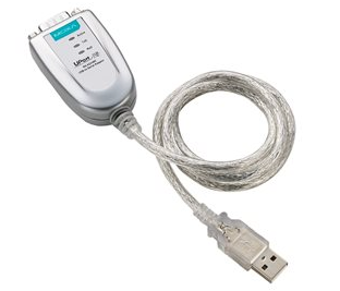
When developing and debugging Modbus RTU devices, experts use specialized software and hardware tools. As for hardware devices, the simplest solution will be RS485/USB converter. Of all the devices of this type, probably the most efficient solution is MOXA UPORT 1130/UPORT 1150. The device is designed to be easy to use and requires minimal skills to be assembled. There are also more complex solutions like Ethernet/RS-485 (for example, NPORT from MOXA).
In practice, when it comes to the development of Modbus RTU devices, slave function is implemented more often. Slave devices include various sensors, controlled relays, I/O modules, etc. Master devices are created less often. In automation networks, the master function is usually performed either by a controller, which already has a Modbus stack implemented, or an OPC Server/SCADA system equipped with a Modbus driver.

We won't consider the development of Modbus stack right in this article. The only thing worth mentioning is the FreeMODBUS library, on the basis of which it is quite easy to build a device supporting Modbus slave functions.

Efficient software for Modbus testing


Testing can be performed on different levels of Modbus device development. The Modbus test software and hardware solutions differ depending on the stage of development and the purpose of testing.
During the development process, a situation may arise when a device receives a request and responds to it (this can be either indicated by the packet reception/transmission LEDs, if such elements are provided in the design, or detected by using a debugger and setting a breakpoint) but the data is not displayed in the terminal or another specialized program. In this case, you will need a dedicated serial port sniffer.

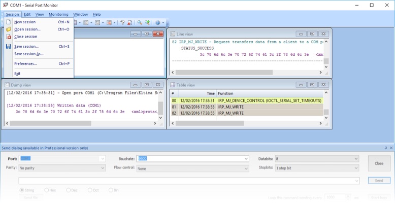
Serial Port Tester is one of the best Modbus monitoring software available today. This Modbus solution can easily read and record any serial data going through the system's COM ports. The advanced functionality of the app allows capturing data in real-time so that a developer can resolve all problems once they have been detected.

COM Port Tester is able to work in the terminal mode that is emulate transferring data from a monitored COM port to a device inserted into it. This option is especially convenient for Modbus communication test, as it allows observing the reaction of a particular device to a specific command and data.

Modbus Tester by Electronic Team, Inc.

Serial Port Monitor logo

Serial Port Monitor

Log and analyze serial port activity
4.8 Rank based on 345+ users, Reviews(345)
Download 14-day fully-functional trial period
Serial Port Monitor

The dedicated software comes in handy when it’s required to not only check whether a device works (that is, correctly respond to requests) but also measure the meantime to failure.

Modbus tester solution allows logging the incoming and outcoming data streams. In addition, all collected data can be shown in different views (table, line, dump, terminal), which makes it simple to compare and analyze it.

Debugging of automation systems based on Modbus devices


There are far more specialists who debug automation systems and devices supporting Modbus protocol than those who develop these devices. So, based on the specifics of tasks, the requirements for Modbus software will be slightly different.

If it is needed to connect a controller to a single slave device, you can establish a serial communication by using RS-485/USB converter, a PC, and specialized software or terminal. In this case, there’s no need for long testing followed by the analysis of numerous log files. So, the logic of the operation and the set of tools will not differ from those used at the testing stage of slave device development.

In case you already have a ready network of devices, the following tasks may be distinguished:

  • checking the operability of all devices on the network (i.e. communication with each separate device and verification of the correctness of its response);

  • load testing (identification of the device’s maximum operating capacity). It is recommended to do several sessions and analyze the collected data for failures, non-responses, data corruption, etc.

To accomplish these tasks, you’ll need either a terminal with the ability to create a list of requests or a specialized tool such as Modbus Poll, a Modbus master simulator that allows monitoring several Modbus slaves and/or data areas at the same time.

Modbus communication challenges


Some of Modbus devices can have particular RS-485 interface settings (the number of data bits, parity, the number of stop bits). Devices with different settings cannot work in the same network with the same master. The most convenient tool for testing and configuring such devices is a terminal program that supports quick switch between pre-installed port parameters or works with several lines simultaneously.

Another challenge is providing data exchange with a device working over a protocol different from the standard specification of Modbus RTU. For instance, the slave's protocol may be logically similar to Modbus (package structure, timeouts, etc.) but use some functions beyond the standard.

In this case, it will be a good idea to use either Modbus Poll, which allows formulating arbitrary requests, or a terminal that supports similar functionality.

Standard SCADA-system is not efficient for working with such devices and communication with the equipment is established over a special OPC server.

Serial Port Monitor

Requirements: Windows (32-bit and 64-bit): Vista/7/8/10/11, Windows Server 2008/2012/2016/2019/2022, Windows on ARM , 9.87MB size
Version 9.5.589 (16 Nov, 2023) Release notes
Category: Communication Application